 TRANSFORMERS & ELECTRICAL COMPONENTS

APPLICATION / 01
Indoor distribution switchgear
For compatible air-insulated switchgear requiring the selected embedded-pole breaker arrangement.
Four product ranges · Manufacturing and coordinated supply
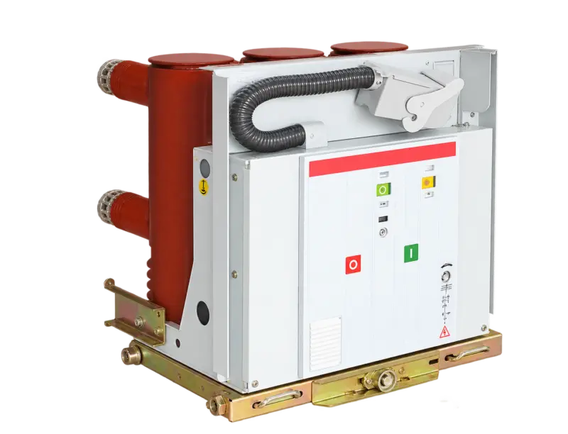
Product illustration. Actual configuration varies by specification.
Open product image ↗Indoor vacuum circuit breaker with epoxy-embedded poles.
Price on enquiry · Configuration, quantity & destination
Supply scope, manufacturer information, applicable documents and warranty arrangements are confirmed in the quotation and order.
MKM65 is an indoor vacuum circuit-breaker arrangement using embedded poles. The vacuum interrupter and principal conducting components are incorporated within the insulating pole construction. Fixed and withdrawable applications require matching electrical ratings, operating functions and mechanical interfaces.
For compatible air-insulated switchgear requiring the selected embedded-pole breaker arrangement.
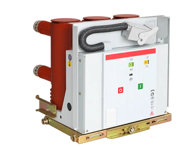
For replacement projects supported by nameplate, mounting, terminal and secondary-interface information.
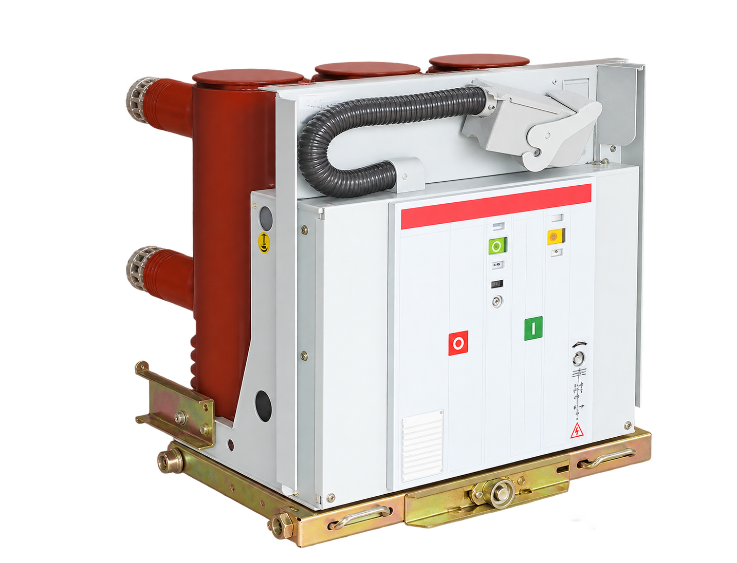
The insulating pole uses epoxy embedding around the interrupter and associated conducting components. Pole construction is a defining feature of this series.
Interruption occurs in the vacuum interrupter. Required breaking duty and operating sequence must match the selected rating.
The operating mechanism is selected with the trip, close and auxiliary circuits. Available control-supply variants must be matched to the installation.
Mounting arrangement and terminal interfaces differ between assemblies. Similar voltage or current ratings do not establish interchangeability with another breaker series.
Match the installation drawing, cable routes, clearances and electrical duty for the selected equipment.
Illustrative working sceneState any different ambient temperature, altitude, humidity, dust, salt or corrosive exposure when requesting the installation-specific configuration.
Review the listed configuration and applicable units. On a small screen, scroll the table sideways.
| Parameter | Catalogue value |
|---|---|
| Rated voltage in table | 12 kV |
| Rated frequency | 50 Hz |
| Lightning impulse withstand | 75 kV |
| 1 min power-frequency withstand | 42 kV |
| Short-circuit breaking current options | 20 / 25 / 31.5 / 40 kA |
| Short-circuit withstand duration | 4 s |
| Closing time | 30–70 ms |
| Opening time | 20–50 ms |
| Mechanical life stated in catalogue | 10,000 operations |
| Stored-energy/operating voltage options | AC 220 / 110 V; DC 220 / 110 V |
| Contact opening distance | 11 ±1 mm |
| Contact overtravel | 3.5 ±0.5 mm |
Checked against original distribution catalogue PDF page 50. Current-to-breaking-capacity combinations and mounting interfaces require a matching variant drawing. Ratings describe catalogue options, not every possible combination; select the complete configuration in the technical schedule.
Send your selected rating and installation requirements to request the matching dimensional drawing, connection details and technical schedule.
Agree the selected specifications, applicable drawings, inspection records and identification requirements in the quotation and order.
Include quantity, destination, packing requirements and preferred trade terms. Confirm transport scope and the requested delivery schedule with the quotation.
For an existing unit, provide its model, nameplate or order reference and a description of the issue. Include relevant photos or records already available. Warranty and service scope follow the agreed order terms.
Contact about this model ↗Choose your enquiry type. Start with the information you have.
Quotations are prepared for the selected configuration, quantity and destination. Currency, validity, delivery terms, freight and any applicable duties or taxes are specified in the quotation.
New installations & project tenders
Discuss a project ↗Specify electrical duty, installation arrangement and the required protection coordination.
Model lists & repeat orders
Discuss supply requirements ↗List complete breaker variants, pole counts, control voltages and accessory combinations.
Equipment integration & matching
Discuss an assembly ↗Provide mounting, terminals, operating mechanism and secondary wiring interfaces.
Identify an existing unit or part
Identify a replacement ↗Start with the complete nameplate and photos of terminals, mounting, secondary plug and accessories.
Illustrative enquiry scenarios.
Testing, warranty terms and after-sales scope are to be agreed in the quotation and order documents for the selected configuration.
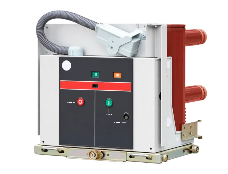
Voltage designation: 12 kV
View specifications ↗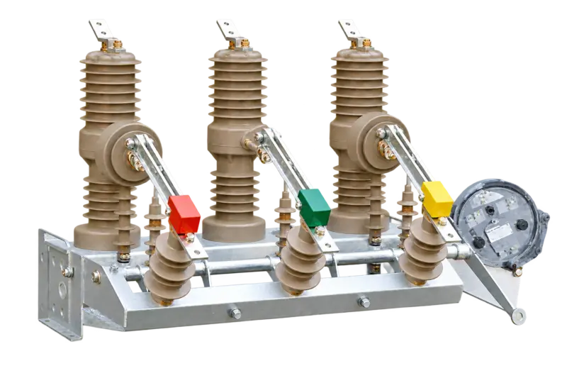
Voltage designation: 12 kV
View specifications ↗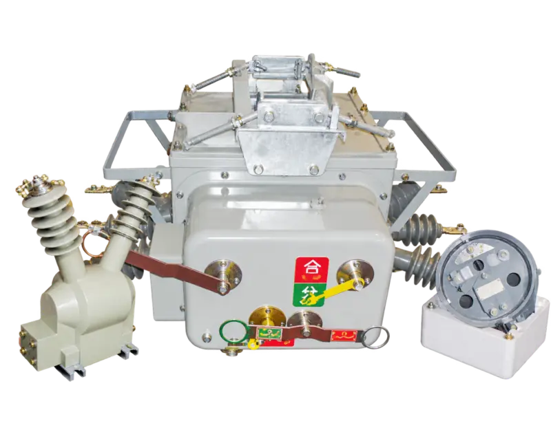
Voltage designation: 12 kV
View specifications ↗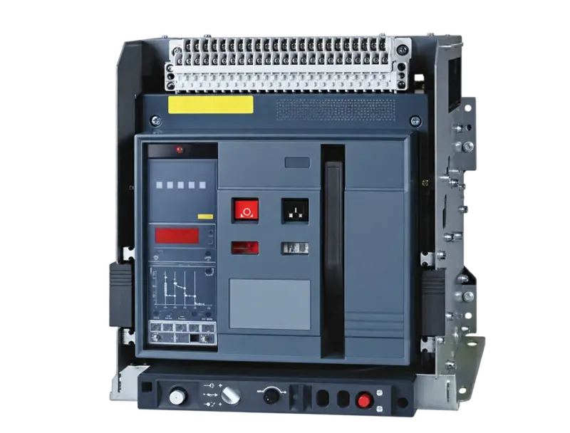
Voltage designation: Low voltage
View specifications ↗Mingkong High & Low Voltage Switchgear Selection Guide · Updated 24 October 2026 · Chinese / English
For a quotation, include your required model, rating, quantity and operating conditions.