 TRANSFORMERS & ELECTRICAL COMPONENTS

APPLICATION / 01
Industrial power and motor distribution
For plant distribution boards and motor-control centres in process, manufacturing and textile installations.
Four product ranges · Manufacturing and coordinated supply
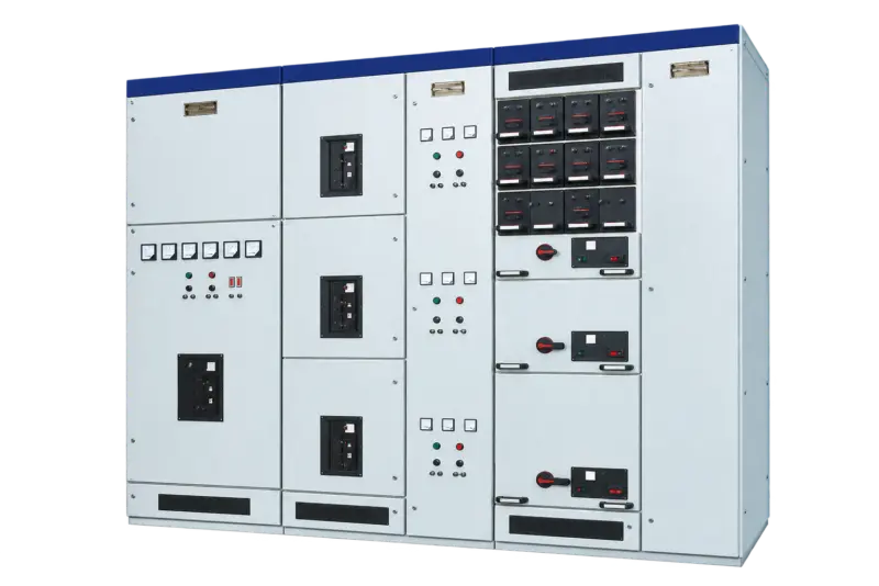
Product illustration. Actual configuration varies by specification.
Open product image ↗Withdrawable low-voltage assembly for distribution, motor control and compensation circuits.
Price on enquiry · Configuration, quantity & destination
Supply scope, manufacturer information, applicable documents and warranty arrangements are confirmed in the quotation and order.
MKCS is a withdrawable low-voltage switchgear system for power distribution, motor control and reactive-power compensation. Its compartmented arrangement allows a project to combine incoming power circuits and outgoing functional units in a coordinated line-up. The feeder schedule determines drawer sizes, protective devices and cable space.
For plant distribution boards and motor-control centres in process, manufacturing and textile installations.

For larger building loads where incoming, outgoing and compensation functions need a coordinated switchboard arrangement.
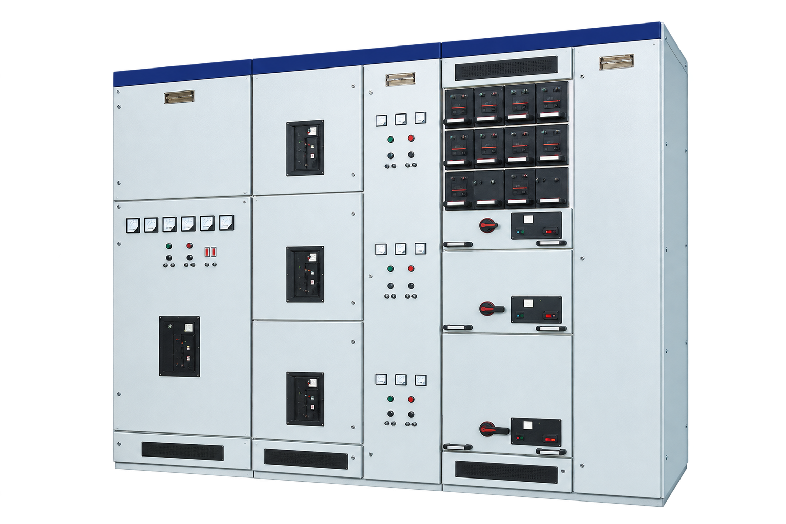
The enclosure uses an 8MF open-profile frame, with assembled or partly welded construction. Frame, doors and internal mounting provisions form the basis for the selected functional units.
Busbars, functional units and cables occupy separate spaces. Rear horizontal busbars and the cable compartment are coordinated with the selected line-up and outgoing circuits.
Drawer units use different module heights to accommodate the circuit duty. Interchangeability applies to matching functional units; it should not be assumed between different ratings or circuit arrangements.
Secondary plug connections support the withdrawable arrangement. Mechanical interlocks coordinate operating and withdrawal states; the final scheme must match the specified switching devices.
Match the installation drawing, cable routes, clearances and electrical duty for the selected equipment.
Illustrative working sceneReview the listed configuration and applicable units. On a small screen, scroll the table sideways.
| Parameter | Catalogue value |
|---|---|
| Main-circuit voltage options | AC 380 / 400 / 660 V |
| Auxiliary voltage options | AC 220 / 380 / 400 V; DC 110 / 220 V |
| Rated frequency | 50 / 60 Hz |
| Insulation voltage options | 660 / 1,000 V |
| Horizontal bus current | Up to 6,300 A |
| Vertical MCC bus current | 1,000 A |
| Short-time bus withstand (1 s) options | 50 / 80 kA |
| Peak bus withstand options | 105 / 176 kA |
| Main/auxiliary power-frequency test voltage (1 min) | 2,500 / 1,760 V |
| Bus system | Three-phase four-wire or five-wire |
| Enclosure protection options | IP30 / IP40 |
Checked against original distribution catalogue PDF page 27. Ratings describe catalogue options, not every possible combination; select the complete configuration in the technical schedule.
Send your selected rating and installation requirements to request the matching dimensional drawing, connection details and technical schedule.
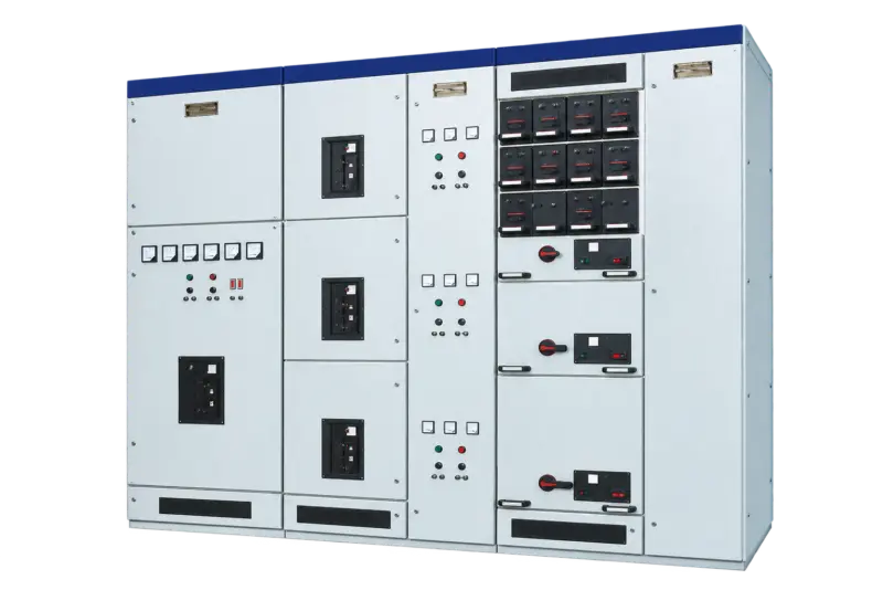
Agree the selected specifications, applicable drawings, inspection records and identification requirements in the quotation and order.
Include quantity, destination, packing requirements and preferred trade terms. Confirm transport scope and the requested delivery schedule with the quotation.
For an existing unit, provide its model, nameplate or order reference and a description of the issue. Include relevant photos or records already available. Warranty and service scope follow the agreed order terms.
Contact about this model ↗Choose your enquiry type. Start with the information you have.
Quotations are prepared for the selected configuration, quantity and destination. Currency, validity, delivery terms, freight and any applicable duties or taxes are specified in the quotation.
New installations & project tenders
Discuss a project ↗Send the load list, single-line diagram, fault duty and switchroom layout.
Model lists & repeat orders
Discuss supply requirements ↗Identify recurring cabinet arrangements, circuit quantities and preferred installed devices.
Equipment integration & matching
Discuss an assembly ↗Supply the feeder schedule, wiring diagrams, mounting details and cable-entry requirements.
Identify an existing unit or part
Identify a replacement ↗Provide cabinet, drawer or device identification, dimensions and connection details for the part to be replaced.
Illustrative enquiry scenarios.
Testing, warranty terms and after-sales scope are to be agreed in the quotation and order documents for the selected configuration.
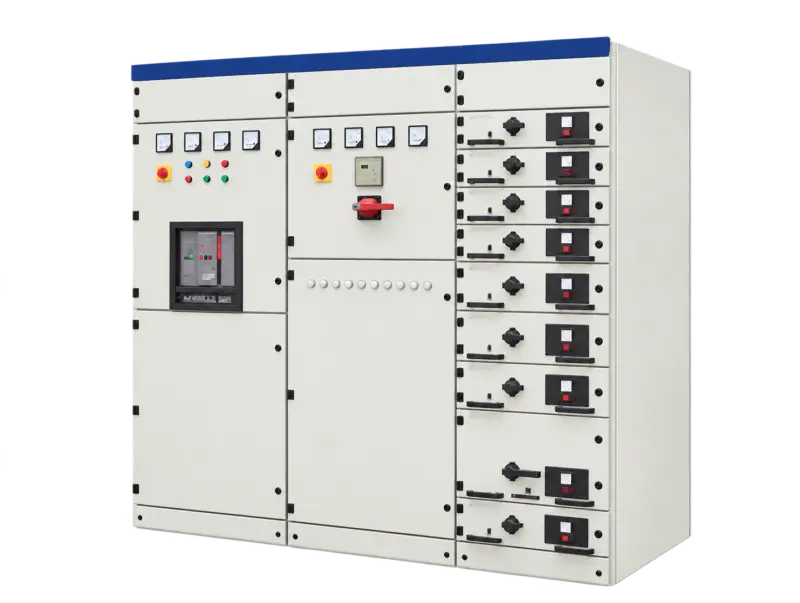
Catalogue designation: 400 V AC
View specifications ↗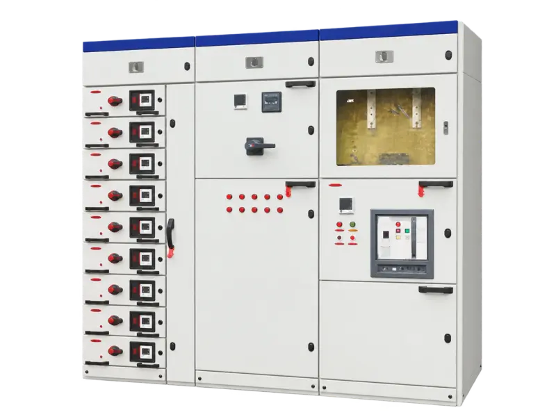
Catalogue designation: 380 / 660 V
View specifications ↗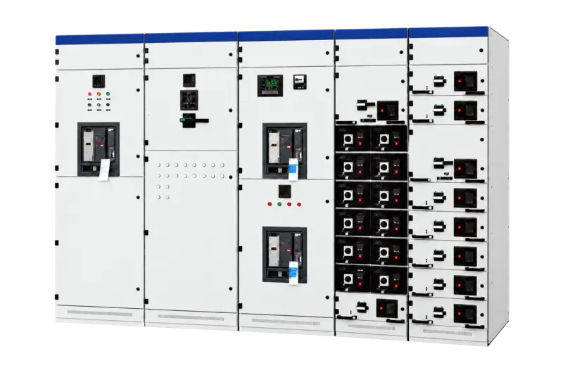
Catalogue designation: 380 / 400 / 660 V
View specifications ↗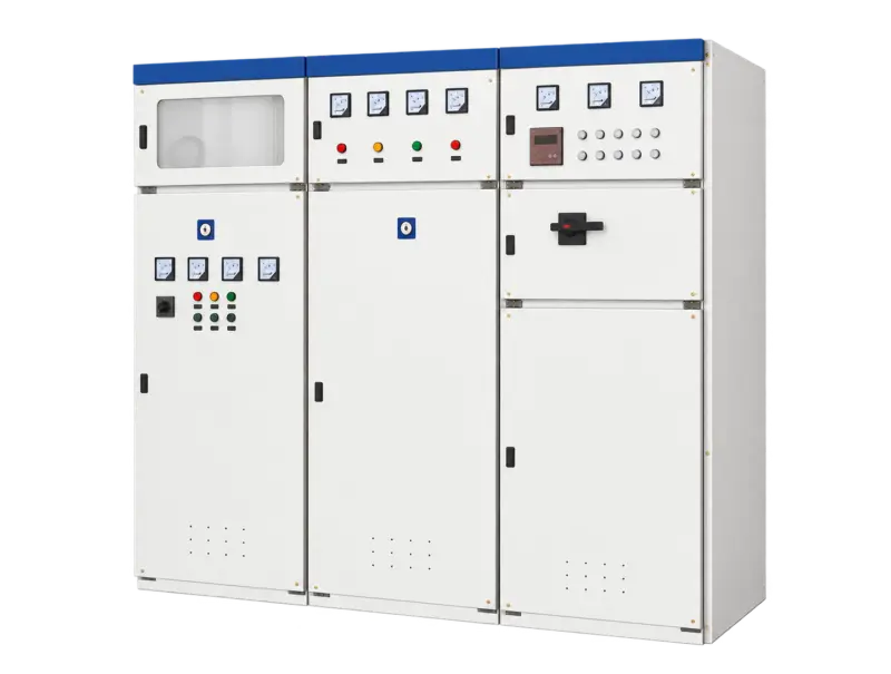
Catalogue designation: 380 V
View specifications ↗Mingkong High & Low Voltage Switchgear Selection Guide · Updated 24 October 2026 · Chinese / English
For a quotation, include your required model, rating, quantity and operating conditions.