 TRANSFORMERS & ELECTRICAL COMPONENTS

APPLICATION / 01
Plant power centres
For incoming supplies, bus distribution and large outgoing circuits serving industrial installations.
Four product ranges · Manufacturing and coordinated supply
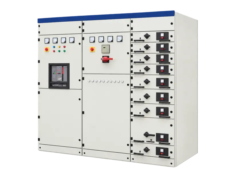
Product illustration. Actual configuration varies by specification.
Open product image ↗Modular low-voltage switchgear for power distribution and motor-control duties.
Price on enquiry · Configuration, quantity & destination
Supply scope, manufacturer information, applicable documents and warranty arrangements are confirmed in the quotation and order.
MNS is a modular low-voltage switchgear system combining power-centre, motor-control and compensation functions. Fixed and withdrawable arrangements can be selected to suit the circuit schedule. The modular structure supports different functional combinations within an agreed electrical and dimensional design.
For incoming supplies, bus distribution and large outgoing circuits serving industrial installations.
For grouped motor-control circuits requiring switching, protection, indication and control interfaces.
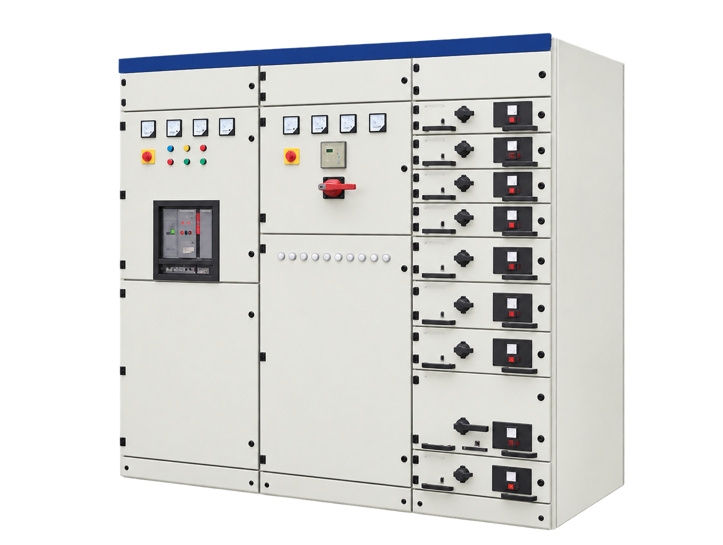
The frame uses a regular mounting-hole arrangement to position internal components and functional assemblies. Galvanised structural parts and finished doors form the described cabinet construction.
Power-centre sections accommodate the main switching and distribution equipment, including withdrawable breaker arrangements where specified.
Motor-control sections may use drawer or fixed functional units. Unit selection depends on the motor duty, starting method, protection and control requirements.
Protection, operation, measurement, indication and control functions can be combined within the switchboard scheme. Compensation sections should be identified separately in the project scope.
Match the installation drawing, cable routes, clearances and electrical duty for the selected equipment.
Illustrative working sceneReview the listed configuration and applicable units. On a small screen, scroll the table sideways.
| Parameter | Catalogue value |
|---|---|
| Rated insulation voltage | AC 690 V |
| Rated operating voltage in table | AC 400 V |
| Rated impulse withstand | 8 kV |
| Rated frequency | 50–60 Hz |
| Main-bus maximum current | 6,300 A |
| Main-bus withstand current | 100 kA |
| Main-bus peak withstand | 220 kA |
| Enclosure protection options | IP30–IP54 |
Checked against original distribution catalogue PDF page 29. The table states 400 V operation; other voltage arrangements require a separate schedule. Ambiguous vertical-bus values are excluded. Ratings describe catalogue options, not every possible combination; select the complete configuration in the technical schedule.
Send your selected rating and installation requirements to request the matching dimensional drawing, connection details and technical schedule.
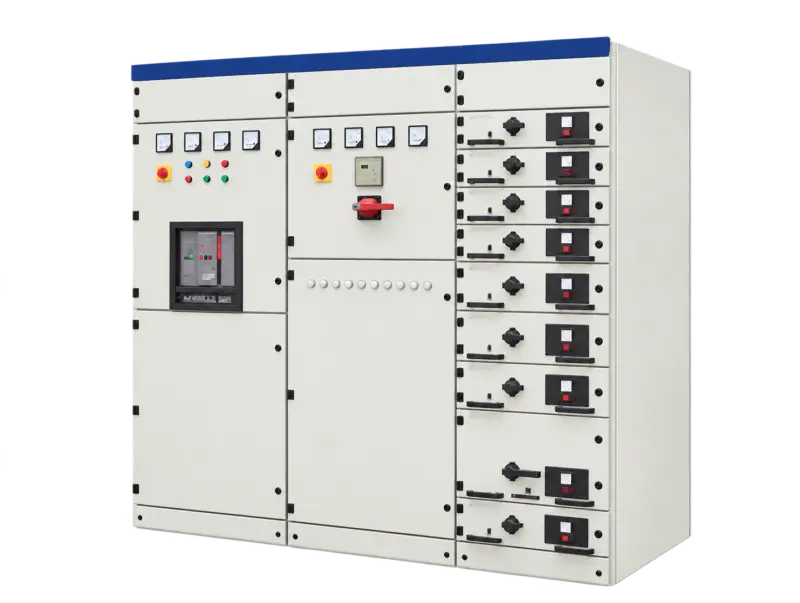
Agree the selected specifications, applicable drawings, inspection records and identification requirements in the quotation and order.
Include quantity, destination, packing requirements and preferred trade terms. Confirm transport scope and the requested delivery schedule with the quotation.
For an existing unit, provide its model, nameplate or order reference and a description of the issue. Include relevant photos or records already available. Warranty and service scope follow the agreed order terms.
Contact about this model ↗Choose your enquiry type. Start with the information you have.
Quotations are prepared for the selected configuration, quantity and destination. Currency, validity, delivery terms, freight and any applicable duties or taxes are specified in the quotation.
New installations & project tenders
Discuss a project ↗Send the load list, single-line diagram, fault duty and switchroom layout.
Model lists & repeat orders
Discuss supply requirements ↗Identify recurring cabinet arrangements, circuit quantities and preferred installed devices.
Equipment integration & matching
Discuss an assembly ↗Supply the feeder schedule, wiring diagrams, mounting details and cable-entry requirements.
Identify an existing unit or part
Identify a replacement ↗Provide cabinet, drawer or device identification, dimensions and connection details for the part to be replaced.
Illustrative enquiry scenarios.
Testing, warranty terms and after-sales scope are to be agreed in the quotation and order documents for the selected configuration.
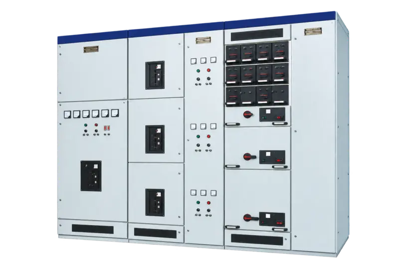
Catalogue designation: 380 / 400 / 660 V
View specifications ↗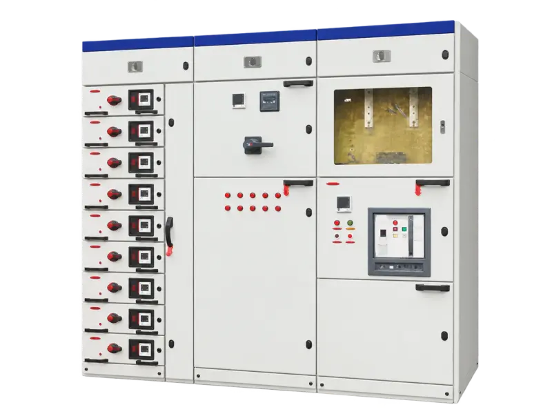
Catalogue designation: 380 / 660 V
View specifications ↗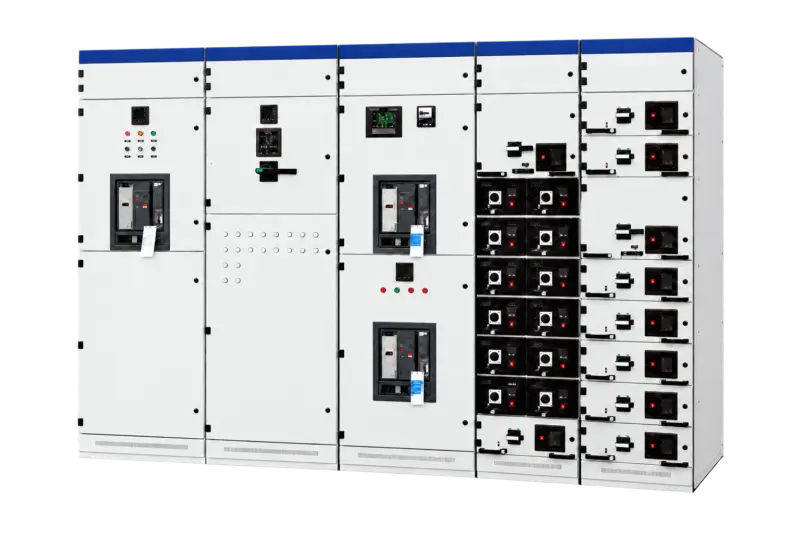
Catalogue designation: 380 / 400 / 660 V
View specifications ↗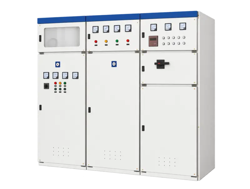
Catalogue designation: 380 V
View specifications ↗Mingkong High & Low Voltage Switchgear Selection Guide · Updated 24 October 2026 · Chinese / English
For a quotation, include your required model, rating, quantity and operating conditions.